Real Jets, Real Cheap -
20th Century technology on a 19th Century budget
[Part I]
Interview with 'Tundra Man'
_____________________________________________________
Note from the Editor:
Many hobbyists are first attracted to pulsejets because of their
seemingly cheap and simple construction. These people are then
shocked when they peruse the Web and find jets on E-Bay costing
hundreds of dollars. Although Bruce Simpson's advanced designs
and David Brill's zinc castings are beautifully designed objects,
they might be considered too pricey for the average backyard
experimenter. Two regular participants at Kenneth Moller's jet
propulsion forums have found some solutions for the penny-pinching
powerplant designer. Read this and the following interview to find
out how they managed to build some astounding machines on some
astoundingly thin budgets. - Larry Cottrill
_____________________________________________________
The Tundra Jet
['Tundra Man' Mike Kirney, interviewed by Larry Cottrill]
The first jet project in our 'Cheapskate Homebrew Showcase' comes
from Mike Kirney, of Renfrew County, Ontario. He is known to
many on Kenneth's forums as "Tundra Man". After reading and
posting on the forum for over two years, he finally decided to
take the plunge and build himself a 1/3rd scale Argus 014 replica.
[Editor's note: The Argus was the engine which powered the famous
V-1 "Buzz Bomb" which Germany used against Great Britain in World
War II. Though primitive by today's standards, the V-1 can
probably legitimately be considered the first production "cruise
missile" ever launched.] According to Mike, The only materials he
purchased for this working model were a 3 x 6 foot piece of 22
gauge steel sheet, a 6 by 50 inch roll of 0.005" stainless steel,
and two rods, 1/8" x 36" [one cold rolled steel, and one brass] -
and ended up with more material left over than what he used for
his engine!
Our interview with Mike took place a few weeks ago [mid-April,
2003] - here's what he had to say about building his mini-Argus
engine:
|
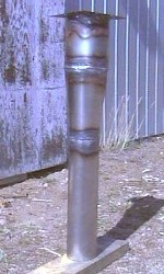
ALL WELDED UP AND NO PLACE TO GO
The fully welded tailpipe assembly of Mike Kirney's
'Tundra Jet'. The square plate at the top end of
the pipe in this photo is the not-quite-finished
'front plate', which provides the mounting surface
where the valve plate will ultimately be attached.
Photo Copyright 2003 Mike Kirney
VIEW LARGE IMAGE
|
jZ: Welcome, Mike! All right, let's get started. How did you
first become interested in pulsejets?
Mike: Back in '99, I was an aircraft maintenance student in
community college. A passing mention was given to pulsejets in
my powerplant textbook. Although the text claimed that the
pulsejet had no practical value as an aircraft powerplant, the
idea of producing hundreds of pounds of thrust from a simple duct
and valve device captivated me. I had no idea how they worked or
what sort of operational idiosyncracies they presented until I
found Kenneth's forum online, a year later.
jZ: How much have you spent on materials for your first engine
project, the 'Tundra-Jet'?
Mike: The steel sheet was $40 CDN, the roll of stainless shim was
$30 and the rods were seven bucks each, for a grand total of $84
CDN. I still have more than 2/3rds of the sheet left and about
4/5ths of the roll of shim. If I bought just a couple more rods, I
could make at least two more Tundra-Jets from the leftover
materials.
jZ: Tell us about the design of this pulsejet.
Mike: I decided to shoot for a duct length (behind the valves) of
100 cm. I just divided all the dimensions of the original Argus
by 3.3 - many forum members advise against such a simplistic
approach but it seemed to make the most sense to me. I wasn't
looking to make a lot of thrust, as I intended to use my jet for
melting snow in my driveway, plus, by adding length to the
tailpipe, I can change the operational characteristics.
HANGING LOOSE
An early shot of Mike's beautiful hand-formed pipe
sections, carefully stacked together before any
welding. This does indeed look almost identical to
the original Argus engine pipe -- only the scale of
surrounding objects reveals the truth.
Photo Copyright 2003 Mike Kirney
|
VIEW LARGE IMAGE
|
|
|
jZ: What about the valve-holder? I know Your intake is a sort of
square steel frame 12 cm on each side, enclosing a grid of
more-or-less square cells to contain the reeds.
Mike: The valve array took the most work to design. I figured my
jet was too big for petal valves. Had I used them, each petal
would have wound up being almost 7 cm long! I wanted to use the
22 gauge sheet for as much of the jet as I could. Eventually I
devised an interlocking set of 10 steel rectangles with tabs and
slots cut in them. The horizontal pieces have two holes drilled
in them, one behind the other, to form a figure-8. I cut pieces
of steel rod 14 cm long and knocked them into the rear-most holes.
These rods I brazed in place. They serve as the permanent half
of valve holders. After placing the reeds in their respective
positions, I then knocked the brass rods into the front holes.
The valves are thus held in place between the two rods, the brass
ones easily removable with a punch pin for reed replacement.
jZ: How will you keep the brass rods in place? I mean, I can
see vibration gradually working them loose, or something.
Mike: I think I'm going to lash them to the steel rods with wire
at each end and then tin solder it all in place. The solder can be
easily removed for maintenance.
![Setup of the valve plate [unbrazed] (c) 2003 Mike Kirney](Mike_setup_valveplate_crop1_small.jpg)
|
A THOROUGH GRILLING
The pieces of the valve grid, carefully set up
before brazing it all together. The steel rods are
vertical in this shot; the brass rods aren't in
place, but they'd lie directly in front of the steel
rods. One folded reed will form a back-to-back
pair of valves in each cell.
Photo Copyright 2003 Mike Kirney
VIEW LARGE IMAGE
|
|
jZ: What did you have to do to actually fabricate your reeds?
Mike: I cut them from the 0.005" stainless shim with ordinary 8
inch long scissors. Each rectangular reed is 6 cm long and 1.5
cm wide. These pieces are bent in the middle so that they rest
like saddles on the steel rods in the array. Each reed
effectively becomes two valves when the brass rods are hammered
into place.
jZ: OK -- let's make sure I really have an accurate mental picture
of this. We have a steel rod permanently set. Each valve reed is a
rectangle folded in the middle to form a V-shaped piece. The point
of the 'V' rests against the rear side of the steel rod, then the
brass rod is slid through behind - or inside - the 'V' to lock it
against the steel rod in front.
Mike: That's it.
jZ: How did you handle the hot metalwork? I believe you've said
you used conventional torches to do the brazing and welding.
Mike: Yes, I did. The first thing I did was clean an area of the
steel sheet with varsol and acetone to get all the grime off.
Then I sprayed it with a light coat of grey automotive primer.
This allowed me to draw easily visible lines on it with an HB
pencil. I used a ruler and a triangle to lay out two rectangles,
which I cut out with a pair of compound leverage shears. After I
removed the primer and pickled the pieces with muriatic acid, I
washed them with dish detergent and water and rolled them by hand
into cylinders which would become the combustion chamber and
tailpipe of my jet. I used an oxyacetylene welding torch to do
all the welding and brazing and some of the cutting.
A BRAZEN ATTEMPT ...
Here's the grid after brazing all the connection
points. Brazing is not necessarily beautiful in its
finished state; the technique is similar to silver
soldering, but at a higher temperature. It is quite
strong, though not equal to welding.
Photo Copyright 2003 Mike Kirney
|
VIEW LARGE IMAGE
|
|
![The entire valve plate completed [brazed] (c) 2003 Mike Kirney](Mike_brazed_valveplate_crop1_small.jpg)
|
jZ: But you cut the sheet metal with hand shears ... wow.
Weren't the cut edges awfully rough and distorted?
Mike: Yes, they were. I cut all my pieces a millimetre or two
oversize and then I filed the edges down to the pencil lines with
a 9" bastard file and an 8" mill file. The shearing and filing
took the most physical energy of all, especially the shearing.
Sometimes I had to brace the shears on my basement floor and step
on them to make the cuts, especially when I was deep into the
material.
jZ: You said you rolled your pieces by hand? Surely you must have
used implements of some kind ...
Mike: I did. I used 4" lineman's pliers to bend one edge of the
rectangle downwards slightly. Then I placed two 1" dowels, one on
either side of the bend and curled my fingers around the inside
dowel. I just rolled up the steel like a piece of paper.
jZ: Like a piece of paper ... hmmmm, right ...
Mike: Well, that's how I got the first edge started anyway. I used
a variety of techniques to form the cylinders. In my mind's eye I
would break up the circumference of the cylinder into quadrants.
I would alternate quadrants, clamping the sheet between the dowels
and bending one quadrant in a little, then the other, all the way
around, until the edges to be butted were about 5 - 8 mm apart.
Then I rolled the bent edge under the flat edge and presto, I had
rough cylinders. I used a bit of 1/4" rope as a way to apply
uniform pressure to cinch the edges together too.

|
FIRST TRY AT WELDING
Another picture from very early on in the project:
The combustion chamber cylinder, with Mike's first
weld [well, the first in a long time, anyway]. Looks
awfully good to me.
Photo Copyright 2003 Mike Kirney
VIEW LARGE IMAGE
|
jZ: Was it difficult to weld your cone and cylinders?
Mike: I did practice a little before I started - it was the first
time I had picked up a torch since college. I used a #0 tip and
about 4 psi on the acetylene. My oxygen regulator was designed
for cutting so it was hard for me to tell just how much pressure
I had in the hose. I estimate about 7 or 8 psi. I used 1/16"
mild steel rod for the welding and 3/32" flux-coated brass rod for
the brazing.
jZ: With a higher oxygen pressure like that, I'd guess you must
have blown through a few times!
Mike: Not really. First I put a tack weld every 12 cm or so down
the length of the piece. Then I heated the rod just enough so
that it would get droopy and stick to the edges to be welded.
After I had laid down a few inches of rod this way, I would go
back and puddle it all together with the base metal. The biggest
problem I had was my workpieces warping and the edges overlapping,
especially with the long tailpipe. This really freaked me out at
first, but in the end it all turned out okay. After welding, I
shaped the cylinders a little more by hammering them over a scrap
piece of wood and squeezing them in my hands and between my knees.
jZ: What about the cone? A lot of people think they know how to
lay out a cone, but then after they roll it together and weld it
up, they find out they were way off the mark!
Mike: That nearly happened to me. Thank God for Hank bringing it
up on the forum. It was his fortuitous comment that made me
realize that I had no idea how to lay out a flat pattern for a
truncated cone. I did a websearch and found a site with a really
good method based on trigonometry. Using that method, I made a
template which I traced onto a piece of cardboard. Then I traced
that onto the steel sheet. I refined their explanation a little
and put it up on my webspace:
http://home.ca.inter.net/mkirney/cone.html
jZ: Why didn't you just use the well-known program called "Cone"?
Mike: I thought about it, but I realized that my developement
would be too big to print on a single sheet of letter-sized
paper. Believe it or not, I actually enjoy doing trig. I wanted
to learn the principles behind the cone development so I could
apply them to other shapes as well.
jZ: You ENJOY trigonometry? Are you psychotic, or what?
Mike: Well, lets just say I am socially functional but as yet,
psychiatrically undiagnosed.
jZ: How can you enjoy trig? Seriously, Mike ... I detect
illness ...
Mike: Hey c'mon Larry. I don't make fun of your little tiny jets.
jZ: Tiny? TINY!!! My engines will ... uh ... fit into any budget
and lifestyle ... they'll uh ... become a novel addition to any
home environment ... um ...
Mike: Yeah, right ... well then, just cut the jive about my trig
fetish, OK?
jZ: Oh, all right, we'll try to get back on topic here. You
mentioned to me earlier that you actually did some cutting with
the welding torch. Isn't that ... illegal or something? [laughing]
Mike: Nope. I used a #2 tip to cut out the circles for the
valveplate and the frontplate on the duct. It was very quick and
easy but I had to file off the inside edges afterwards.
jZ: Yes, actually my dad had a rather nifty trick for that. He'd
heat a spot up red hot with the torch, then quickly valve off
the acetylene and just start moving it along, letting the oxygen
stream keep the cut going. It was an amazing thing to see! Now,
you have a frontplate that acts as a mounting surface for your
valveplate, right? That's pretty heavy stuff compared to the
sheet metal chamber -- I mean, welding the frontplate to the
combustion chamber must have been a bit of a blacksmith's
nightmare, I would think.
Mike: Nah, it was easy. I used the same technique as before
where I laid down the rod and then puddled it after. There was
some overlap left on the inside of the hole so I just puddled
that down to a nice round edge. That joint is probably the
strongest one on the whole engine.
jZ: How do you attach the valveplate to the rest of the jet?
Mike: I use eight 5/16" bolts with nuts and lockwashers. They
are about an inch long so they should accomodate any gasket I might
have to use.
TAKING THE LONG VIEW
Looking rearward through the fully welded engine,
as seen through the mounted valve plate grid. Note
the slight out-of-round distortion -- while almost
inevitable when fabricating all the parts by hand,
this should have absolutely no effect on running
or performance.
Photo Copyright 2003 Mike Kirney
|
VIEW LARGE IMAGE
|
|
|
jZ: So ... when do we get to hear this beast run?
Mike: Well, the chinook just blew through town today so that
usually means we're gonna get one more snowfall this week, then
the frost is over until Hallowe'en. I'm hoping I'll have
everything good-to-go by the end of April. I'm trying to adapt a
fuel system from a 1 lb. propane bottle and an old welding torch
I found in my shed. I have an old regulator too. I'm thinking
about just using fireplace matches to light the thing, as
electric starting seems kind of decadent right now.
jZ: Oh, before I forget ... thanks for getting an interview for us
with our friend, Mark 'Thixis'. I'll try to publish that right along
with this one.
Mike: Yeah, Mark's always fun to talk to -- and that dude really
builds some weird stuff ... he gets it to run, though!
jZ: Well I hope you keep in touch, Mike. I mean, we're going
to be hanging from the rafters by our fingernails waiting for your
test results! The Tundra-Jet sounds like it's bound to cause a shop
class revolution.
Mike: [laughing] Ha! Shop class revolution -- I could really dig that!
Thanks for interviewing me, Larry. Hey man, I saw some empties under
your front deck. Would you mind...?
jZ: What, those old Pepsi cans? Uh, yeah, whatever ... go ahead
and take 'em.
Mike: Thanks, man ... you just never know what you can use. See,
I just now thought of this little jet where you'd ...
_____________________________________________________
Photo Credits:
All photos in this article were provided by, and are property of,
Mike Kirney.
_____________________________________________________
 |
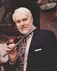
Mike Kirney, of Renfrew County, Ontario, Canada has been
interested in pulsejets for several years, but only started
to build his own a few weeks ago. Mike has also played guitar
[the instrument shown here is a Godin electric from Quebec],
piano, flute and alto sax. He has visited all ten Canadian
provinces and about 20 States of the US, and once bicycled
from Vancouver, BC to San Francisco, CA in nineteen days.
He is very interested in alternative power sources, especially
some new uses for steam. Mike answers to the nic "Tundra
Man" and can be reached at ame2000@lycos.com
Photo Copyright 2003 Mike Kirney
|
_____________________________________________________
|
Real Jets, Real Cheap -
20th Century technology on a 19th Century budget
[Part II]
Interview with Mark 'Thixis'
_____________________________________________________
Note from the Editor:
There's more than one way to build working pulsejets 'on the
cheap'. In the previous article, Mike Kirney showed how low cost
materials can be used effectively; however, Mike's building
techniques still require a lot of manual skill and effort -
especially, skills in metal forming and gas welding. The
following article shows a completely different method. This
does not produce lightweight 'flight engines' [which is what a
lot of us kind of expect a jet engine to be] but rather, simple,
extremely rugged structures, built mostly of ordinary plumbing
parts -- what this builder calls a 'Tinker Toy' approach. As
you'll see, it's something really different! - Larry Cottrill
_____________________________________________________
Welding? Who Needs Welding To Build a Jet?
[Mark 'Thixis', interviewed for jetZILLA by Mike Kirney]
Here's the other entry in our 'Cheapskate Homebrew Showcase':
Mark 'Thixis', another participant on Kenneth Moller's
pulsejet forum, has constructed an amazing array of simple
pulse combustors using only inexpensive steel pipe and cast
iron plumbing parts, mostly without precision machining. Mark
lives in the State of Florida, USA. Here he's interviewed for
jetZILLA by Mike Kirney [see my interview with Mike, above]
and answers some good questions for amateur pulsejetters:
jZ: How's the weather down south, Mark?
Mark: It's great, Mike! The Spanish Moss is hanging long and I
can eat my fish now instead of running my sled on it.
jZ: Uh ... I beg your pardon?
Mark: Read my forum posts -- you'll figure it out.
jZ: Um, OK ... I'll do that. You have quite a collection of
homemade jets. How long have you been experimenting with pulse
combustion?
Mark: I have been doodling with pulsejets for about 15 years.
|
THE 'THIXIS' FAMILY PORTRAIT
Except for the original DynaJet [the
engine with the red anodized valve head,
near the center of the photo], all these
are experimental engines and 'jam jar'
combustors Mark has built or modified
from such things as plumbing hardware
and medical implements [and, in some
cases, even glass jam jars!].
Photo Copyright 2003 Mark 'Thixis'
VIEW LARGE IMAGE
|
|
jZ: Wow! That's a lot of experimental experience. What got you
interested?
Mark: Long ago my brother gave me a Dynajet that he bought in
Texas for around $60.00. I didn't fire it up for several years.
Then I did, and was surprised at the noise. Later, in college,
I started to wonder if I could build one out of water pipe, and
it took me a few months of thinking and toying until I got one
to run.
jZ: What's the biggest jet you've ever built?
Mark: The biggest jet I attempted was a 4 inch plumbing pipe
which weighed over 40 pounds and was a beast which shook my
garage wall, along with all the things hanging on it, when it
fired. I cowered and decided the neighbors would complain if I
kept the cannon shots up.
jZ: Man! You're lucky you didn't get busted! Did it sustain
combustion?
Mark: No, the biggest I've gotten a continuous run from is
three inch diameter [75mm ID], thick-as-can-be threaded
water pipe.
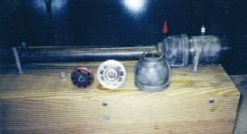
MARK'S BIG IRON
This is the 3-inch pipe engine
mentioned above. The valve plate
shown in this month's cover photo
and in the photos below are from
the front end of this engine, and
can be seen from the valve side at
the center of this shot. The reddish
object is the valve head of the
DynaJet, shown here for scale.
Photo Copyright 2003 Mark 'Thixis'
|
VIEW LARGE IMAGE
|
|
|
jZ: What fuel do you use in your jets?
Mark: I like to use methanol. It evaporates quickly and is very
forgiving with fuel/air ratios.
jZ: Tell me about your first jet. How much did it cost?
Mark: My first jet cost me about $10.00 in parts if you don't
count the spring steel, which was about $20.00 a roll, but you
can make a lot of reeds out of it.
jZ: A jet for thirty bucks US! What tools did you use to build
that thing?
Mark: The tools I used were a grinder, drill press, vise, pipe
wrench, and a tap for the spark plug. A very smooth edge can be
made on a valve plate by inserting a bolt in the middle of the
plate and rotating the disk against an edge in order to control
the distance.

|
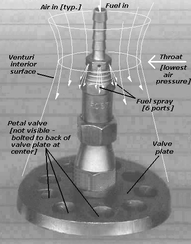
A PLATEFUL OF HOLES ...
Mark's 'bench grinder machined' valve plate at the
bottom, with the fuel port assembly, built up out of
hardware store plumbing parts, bolted to the center.
The ring of nine holes in the plate lets air/fuel mixture
into the combustion zone when suction opens the thin
spring steel petal valves [see bottom view, next photo].
Photo Copyright 2003 Mark 'Thixis'
VIEW LARGE IMAGE
|
|
... AND A FLOWER OF NINE PETALS
Here's the valve plate back side, with the
nine valve petals clamped in place under the
retainer [the large washer in the center] --
the central bolt not only holds the retainer,
but goes clear through the plate to support
the fuel port assembly shown in the photo
above. The front side of the retainer is
dome-shaped to allow the petals to open
rearward and land on its smooth surface.
Photo Copyright 2003 Mark 'Thixis'
|
VIEW LARGE IMAGE
|
|
![The entire valve plate completed [brazed] (c) 2003 Mike Kirney](Mark_valveplate_detail_crop1_small.jpg)
|
jZ: Thanks for the 'machining' tip, Mark. The classic 21st Century
pulsejet is fabricated from thin guage stainless steel sheet. The
heat produced by operation can make these glow brilliant orange.
Does the thick steel wall of the plumbing pipe glow ever like that?
Mark: Even though they are very thick, they glow a dull red, and
if mounted on a board with nails to wedge it down, the board will
billow smoke from the heat.
jZ: Sounds dangerous! What about the zinc coating? Most plumbing
pipe is galvanized, is it not?
Mark: It is. Once I found a deposit at the tail of a 3 inch
diameter water pipe jet. It had formed or melted a ring of zinc
or something that I pulled out almost in one piece from the
galvanized plumbing pipe after it cooled down. I had previously
attempted to grind a flare in the tail [which didn't work with my
tiny grinding stones] so I know the ring wasn't there to begin
with. The ring of metal was soft and bendy.
________________________________________________________________
CAUTION! Precautions need to be taken when using galvanized or
cadmium plated steel in a pulsejet. When the steel gets red hot,
the galvanizing or plating will start to burn off -- the
smoke-like fumes from this are EXTREMELY hazardous to breathe.
When welding such materials, always provide adequate air
movement to keep these fumes away from your face [a small 'box'
fan is adequate] or better yet, work outside and orient the work
so the breeze immediately blows the fumes away from the weld
area. When running your jet the first few times, stay on the
upwind side so the smoke and fumes aren't blowing toward you.
When the engine has been hot enough long enough, the galvanizing
or plating will be completely burned off, so this hazard is
eventually eliminated. - Editor
_________________________________________________________________
|
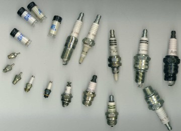
NOW, A FEW SHAMELESS PLUGS
Mark's collection of ignition plugs that
he's used in various homebuilt engines.
Note that some of these are extensively
modified! [The three little plugs at the
left edge are model airplane glow plugs,
for scale. In general, little success has
been achieved by anyone trying to use
glow plugs for pulsejet ignition.]
Photo Copyright 2003 Mark 'Thixis'
VIEW LARGE IMAGE
|
|
jZ: What's the longest one of your jets has actually sustained
combustion?
Mark: The longest I ever ran one was for about 5 minutes, when I
decided to go ahead and let it run the tank dry.
jZ: That's a pretty decent run, as far as I can tell. Thanks for
dropping by to answer some questions for JetZILLA, Mark.
Mark: No problem, Mike. Hey buddy, do you have another beer?
jZ: More beer? Who do you think I am, Molson Breweries? Get outta
here!
Mark: OK, OK. Um ... would be it be alright if I left my truck
here overnight?
|
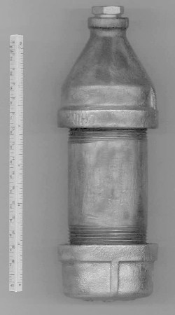
RUGGEDER THAN YOUR AVERAGE JAR
One part of Mark's pulsejet hobby is making up
'jam jars'. A jam jar is an 'almost pulsejet' which
sits upright with a small pool of liquid fuel at
the bottom, and runs by alternately firing and
breathing through a single small nozzle at the
top, after lighting with a match. Traditionally,
jam jar engines are made from a small glass jar
[or more recently, plastic bottle] with a metal
lid in which a small hole has been drilled or
punched. Mark likes his a little heftier; the
ruler on the left is a six-inch [approx. 16 cm]
rule.
Photo Copyright 2003 Mark 'Thixis'
|
|
_____________________________________________________
Photo Credits:
All photos in this article were provided by, and are property of,
Mark 'Thixis'.
_____________________________________________________
Mark 'Thixis' is a longtime pulsejet builder and experimenter
living in Florida, USA. No one knows what his last name really
is, and nobody knows what 'Thixis' really means. But, if you
want to contact him about this article, email: Thixis@aol.com
_____________________________________________________
|