|
The Non-Mathematician's Guide To
Basic Valveless Pulsejet Theory
© 2008 Larry Cottrill
by Larry Cottrill 25 Sep 2008
Section 03.03.03
Letting Up
The odds are strongly against getting air pressure to stay above normal indefinitely
in an acoustic device like a pulsejet, so
now it's time to look at the "trailing" pressure front, i.e. descending pressure. This is
a case where "reversability" applies, and it turns out that this is, indeed, exactly the
opposite action to what we just saw at the "leading" wave front. Of course, this means
we are coming to the problem with a very different starting condition: the air is already
compressed and moving forward at the speed established by the action of the "leading"
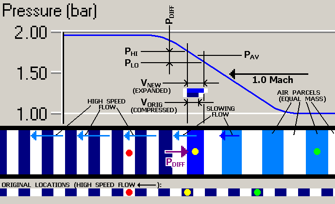
front. We see this in the bottom "original locations ruler", which now shows up as a series
of highly compressed parcels that are moving leftward (note the HIGH SPEED FLOW
vector just above the ruler) -- again, the meaning is that this is where the parcels
would have been if the wave front had not just traversed this region:

Again, we have "marked" selected air mass parcels with colored dots; note that these are
not meant to be the same parcels marked in the earlier graph. Looking at the
yellow-dotted parcel, we see that as the falling pressure front passes, a pressure
difference is again developed, due to the parcel length in the pipe. This time, however,
the higher pressure PHI is acting on the left side of the
mass and the lower pressure PLO is acting on the right.
Because of this, the vector PDIFF is shown acting
rightward on the parcel (in the pipe section of the drawing), so the acceleration
of the parcel is toward the right end. This results in slowing motion of the parcel as
the wave passes, as indicated by the vectors labelled SLOWING FLOW, and also the
displacement of the parcels rightward (note the locations of the yellow- and green-dotted
parcels relative to their "original" positions on the ruler). In fact, in this case, the
masses have returned to a stationary state (relative to the pipe wall)!
For this restoration to zero speed to be achieved, there also has to be a re-expansion
of the masses; in fact, they need to be restored to exactly their original condition
of pressure, temperature and density. This happens automatically as PAV
decreases with the passage of the front across the parcel. At the end of the process,
perfect restoration of the original air condition is complete, and the original velocity
(in this case, zero) is attained. Hence, the initial speed SpeedcondA
is what is denoted by the HIGH SPEED FLOW vectors in the drawing. Since the trailing
wave front is moving along the pipe at 1.0 MachcondB and the pressure
returns to its original value of exactly 1.0 bar, SpeedcondB will turn
out to be zero, for this example. The trailing edge of the wave has taken up the kinetic
energy that once appeared as forward motion and elevated temperatures of the masses that are
now left behind.
The same table used above to show the relationships of pressure, temperature and speed for
the increasing pressure wave front also applies here to the decreasing pressure
front, except that we must switch the CondA and CondB subscripts, because in
the present case Condition A is the compressed high velocity condition, and Condition
B is the restored normal air condition (in this case, stationary in the pipe).
One other fact should be mentioned here, to make sure we're perfectly clear on the total
concept: Even though the passage of the trailing wave front has restored the air to its
original condition and velocity, it has not restored the masses to their original
locations! The wave taken as a whole has in fact succeeded in displacing all
the air mass it passed through significantly leftward. The magnitude of this displacement depends
on the degree of compression achieved (i.e. the pressure difference between the original
and pressurized conditions) and the duration of the pressure difference (essentially, the
length of the wave, front-to-front).
The importance of this is to understand that it takes both pressure and time to perform
the work of moving the air mass along. A lengthy low-pressure wave may move air mass
more effectively than a much more intense high-pressure pulse! This is a lot easier to see
with a wave that is a smooth plateau between two short ramps than it is with the kind of wave
shapes in a real life acoustic device, but the principle is the same. The wave really does
displace mass, and that means actual work is accomplished by the wave passage (in other words,
power is actually involved, just as it takes power for a fan or compressor to move some volume
of air mass per unit time). Down the road, we'll see more "macroscopic" examples of how this
works over large parts of the acoustic cycle time.
Go back to select
another Section
Next Section: Air
Flow Lite
|