Metals in Pulsejet Interiors -
Destructive Tests Reveal the Truth!
by Larry Cottrill
_____________________________________________________
Note from the Editor:
I have been interested for a long time in trying to get stream
momentum measurements of pulsejet gases by using ordinary pressure
gauges. I initially assumed that a tubular stainless probe could
go deep into a running pulsejet without difficulty, and
communicate pressure to an external gauge. What I mainly proved in
trying this is that putting metal structures fully inside the
exhaust stream of a pulsejet is more of a problem than most of us
amateur builders imagine! Here's part of what I posted on Kenneth
Moller's Pulsejet Forum on May 6, 2003:
III. Internal metal structures are going to have problems
Unless you are willing to use exotic materials [maybe Titanium
would have held up OK?] or go to extremes of complexity [e.g.
forced cooling of internal parts?], internal structures imposed in
the hottest parts of a pulsejet are doomed to failure – in some
locations, instantaneous failure! My hypothesis is that such parts
are extremely limited in their ability to radiate excess heat, and
easily reach welding temperature [yellow or white hot]. At such
temperature, stainless is readily oxidized in air. I hypothesize
that the DynaJet, in its stock configuration, handles a good deal
of ‘excess air’ [air not absorbed in combustion], at least during
the earliest parts of the combustion cycle, and this air is
available for oxidation of the extremely hot material. Stainless
does not oxidize appreciably at red heat, which is why the air-
cooled outer shell of the engine doesn’t suffer burn-through, even
in static running without forced cooling.
Here's what we learned in more careful subsequent testing of
metal samples. Take a look at what happens! - Larry Cottrill
_____________________________________________________
Why bother with these tests?
The main reason I wanted to test different metals deep inside
a running pulsejet is my desire to attempt pressure gauge
measurements at different points in the tailpipe. I first
tried measurements using an automotive fuel pressure/suction
gauge connected to about a metre length of small stainless steel
tubing, bent to act as a probe to be pushed into the tail of
the engine. This gave some very interesting results as far as
the gauge readings were concerned, but once the SS tubing was
shoved fairly far forward, the tubing began to disappear in a
shower of white hot sparks from the tailpipe! Clearly
unacceptable.
My conclusion was that my basic method of measurement was
sound, but that a much more stable metal would be needed for
such punishing experimental conditions! Some recent posts
on the Pulsejet and Valveless Forums had expressed interest in
getting metal structures set up inside pulsejet exhaust streams.
So, I felt that we really needed to try some basic tests of  a few different practical materials.
A simple test methodology
Ben Brockert and I got together on Saturday, May 24, 2003,
to do more investigation of the bahavior of structural
metals immersed in pulsejet combustion gas streams. The
general plan was to start out with each sample barely inside
the pipe, and then incrementally go farther in with each test
run. Basically, we tested each sample 1 inch inside the pipe,
6 inches inside the pipe, and 9 inches inside. [We started
out with the idea of a smaller increment, but it would have
taken more runs of the engine than even my neighbors could be
expected to tolerate in a single afternoon!] In each case, I
tried to position the tubing under test parallel to the
tailpipe wall and in a "middle zone" between the center of the
pipe and the wall. Engine runs varied from under 15 to over 20
seconds, mostly depending on how much difficulty was
encountered [and hence, fuel wasted] in starting.
THIS IS A SETUP, I TELL YA! IT'S ALL A SETUP ...
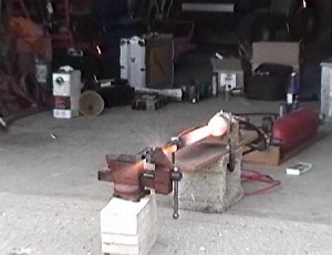
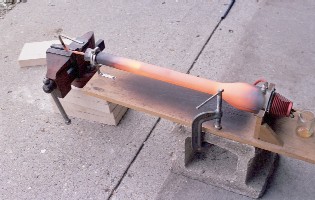
Our basic test setup is simple, almost to the point of being crude, but with care we
can get the sample positioned and aligned in minutes. The small vise at the left
supports the metal tube sample within the tailpipe of the DynaJet. At the far right,
note the glass jar 'fuel cell', the air hose connected to the 'flowjector' and the
high voltage leads still connected to the spark plug [energized only for starting].
The sample here is 1/2-inch [13mm] OD mild steel tubing, as described in the text,
positioned only about an inch [25mm] inside the end of the pipe, in this case.
Photo Copyright 2003 Cottrill Cyclodyne Corporation
The first thing we tried, though, was to re-run the
stainless tubing [1/4 inch OD] to duplicate our last effort,
so I could try to get a still photo. This wasn't highly
successful, because the outpouring of sparks is not a very
steady phenomenon, but rather comes in fits and starts, so
you can't predict when a really good fountain of sparks is
going to be there so you can trigger the shutter. This was a
continuing problem during the whole test session, though Ben
did get some dramatic video shots of sparks blasting out and
going all over the place. Here's a series of still shots my
friend, avid R/C flyer Kevin Day, captured from the exciting
video of one run using steel tubing - the stainless tubing
run was very similar in behavior and appearance to what you
see here:
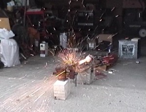
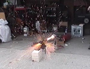
TAILPIPE FIREWORKS
Some still shots made from the video of the first run where erosion of mild steel was
observed. The tip of the tube was approx. 9 inches [230mm] into the tailpipe. After
a large burst of molten metal shown in the top picture, there begins a brief phase of
hot metal vapor emission with practically no sparks [second picture]. Soon, though, we
see further explosions of molten droplets, along with some brightly colored vapor [third
and fourth pictures]. Destruction of stainless steel was just as dramatic. The video was
shot by Ben Brockert on a 'Hi-8' tape cassette; the stills were digitally processed from
the video by my friend Kevin Day, working from a slow-motion copy he generated
especially for this project. Video is almost ideal for analysis - while the engine is
overexposed due to the camcorder's high sensitivity to infrared, this same quality
ensures that even the tiniest sparks are made visible.
Photos Copyright 2003 Cottrill Cyclodyne Corporation
Steelyard blues
For the first real test run, I set up a mild steel tube of
0.5 inch [13mm] OD and about .070 [1.8mm] thickness; this is
many times more massive per inch than the stainless tube,
but it was the smallest I could obtain easily. It held up
fairly well until about 9 inches [230mm] into the tailpipe,
where erosion began to occur. One side of the tube, the side
closest to the tailpipe wall, remained almost unaffected, so
the overall length of the tube didn't change. The innermost
side was eroded back perhaps 0.5 inch [13mm], however, in a
fairly smooth semi-elliptical pattern. A couple of inches
behind this burned edge, there is a ridge of metal welded to
the pipe, with the area in between staying fairly clean. Ben
observed that there was a similar ridge of weld metal on the
INSIDE surface as well. Advancing the tube farther in
resulted in continuing erosion of the affected area, but
still left the outermost edge of the tube more-or-less
unaffected. The erosion observed was much less than we had
experienced with the stainless tubing, but of course, this
was much heavier material to start with, so it may not
constitute a very fair comparison. The important thing is
that severe erosion of fairly heavy walled tubing was
observed, at a moderate distance into the tailpipe.
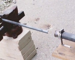
A WEARING EXPERIENCE ...
Results from the first run where erosion of mild steel was observed. The tip of the
tube was approx. 9 inches [230mm] into the tailpipe. The near edge of the tube was
reasonably close to the tailpipe wall, and suffered no noticeable deterioration; the
far edge was close to the center, in the highest velocity part of the flow, and was
seriously eroded away. Some of the metal 'slag' from the melting and burning of the
steel can be seen welded on about 1.5 inches [38mm] behind the rim of the tubing;
most of this material was simply ejected as white-hot sparks, however.
Photo Copyright 2003 Cottrill Cyclodyne Corporation
Getting exotic
The thing we were aching to try, of course, was the Titanium
alloy tubing kindly supplied by Mark 'Thixis'. When this was
tried only an inch inside the pipe, the first thing I
noticed was that this very thin, light tubing doesn't get up
to red heat very quickly - not at all what I expected. The
tubing does cool fairly quickly when extracted from the
tailpipe, due to its very low mass [and hence, low heat
content]. It was not possible to immerse the Ti tubing as
far into the pipe as the steel tubing, because these pieces
are scrap 'end cuttings', most less than a foot in overall
length. The deepest we could get them in was about 10 or 11
inches [260 to 280mm], but we had already seen stainless
completely destroyed at that depth, so we could at least
consider this a fair comparison.
REMEMBER THE TITANIUM!
A test of 1/4-inch [6mm] OD Titanium tubing, at a moderate depth in the tailpipe.
Note the 'hot spot' on the stainless shell of the DynaJet, showing clearly where the
end of the sample tube is positioned. Also note the red heat of the tubing back in
the vise jaws, where exhaust is running around and through it. A 20-second run of the
jet showed absolutely no erosion of the sample metal whatsoever. The tubing is so light
that a sample this size held in the hand feels no heavier than a plastic drinking straw,
yet its bending strength when cold resembles high-strength steel! It is amazing stuff,
but is one of the most expensive alloys you can buy. Small scraps of various sizes
occasionally appear on e-Bay, making it affordable for the serious experimenter.
Photo Copyright 2003 Cottrill Cyclodyne Corporation
There was NEVER an indication of any material erosion of
any kind or degree during testing of the Ti alloy tubing! I
find that totally amazing, considering the thinness and
lightness of the metal tested. When pulled from the deepest
test we could do, the tubing was good and red hot. When it
cooled, it was noted that it was covered with a THIN shell
of lightly attached oxide [or something] which can be flaked
off by gentle finger pressure. This is dark grey [almost
a few different practical materials.
A simple test methodology
Ben Brockert and I got together on Saturday, May 24, 2003,
to do more investigation of the bahavior of structural
metals immersed in pulsejet combustion gas streams. The
general plan was to start out with each sample barely inside
the pipe, and then incrementally go farther in with each test
run. Basically, we tested each sample 1 inch inside the pipe,
6 inches inside the pipe, and 9 inches inside. [We started
out with the idea of a smaller increment, but it would have
taken more runs of the engine than even my neighbors could be
expected to tolerate in a single afternoon!] In each case, I
tried to position the tubing under test parallel to the
tailpipe wall and in a "middle zone" between the center of the
pipe and the wall. Engine runs varied from under 15 to over 20
seconds, mostly depending on how much difficulty was
encountered [and hence, fuel wasted] in starting.
THIS IS A SETUP, I TELL YA! IT'S ALL A SETUP ...
Our basic test setup is simple, almost to the point of being crude, but with care we
can get the sample positioned and aligned in minutes. The small vise at the left
supports the metal tube sample within the tailpipe of the DynaJet. At the far right,
note the glass jar 'fuel cell', the air hose connected to the 'flowjector' and the
high voltage leads still connected to the spark plug [energized only for starting].
The sample here is 1/2-inch [13mm] OD mild steel tubing, as described in the text,
positioned only about an inch [25mm] inside the end of the pipe, in this case.
Photo Copyright 2003 Cottrill Cyclodyne Corporation
The first thing we tried, though, was to re-run the
stainless tubing [1/4 inch OD] to duplicate our last effort,
so I could try to get a still photo. This wasn't highly
successful, because the outpouring of sparks is not a very
steady phenomenon, but rather comes in fits and starts, so
you can't predict when a really good fountain of sparks is
going to be there so you can trigger the shutter. This was a
continuing problem during the whole test session, though Ben
did get some dramatic video shots of sparks blasting out and
going all over the place. Here's a series of still shots my
friend, avid R/C flyer Kevin Day, captured from the exciting
video of one run using steel tubing - the stainless tubing
run was very similar in behavior and appearance to what you
see here:
TAILPIPE FIREWORKS
Some still shots made from the video of the first run where erosion of mild steel was
observed. The tip of the tube was approx. 9 inches [230mm] into the tailpipe. After
a large burst of molten metal shown in the top picture, there begins a brief phase of
hot metal vapor emission with practically no sparks [second picture]. Soon, though, we
see further explosions of molten droplets, along with some brightly colored vapor [third
and fourth pictures]. Destruction of stainless steel was just as dramatic. The video was
shot by Ben Brockert on a 'Hi-8' tape cassette; the stills were digitally processed from
the video by my friend Kevin Day, working from a slow-motion copy he generated
especially for this project. Video is almost ideal for analysis - while the engine is
overexposed due to the camcorder's high sensitivity to infrared, this same quality
ensures that even the tiniest sparks are made visible.
Photos Copyright 2003 Cottrill Cyclodyne Corporation
Steelyard blues
For the first real test run, I set up a mild steel tube of
0.5 inch [13mm] OD and about .070 [1.8mm] thickness; this is
many times more massive per inch than the stainless tube,
but it was the smallest I could obtain easily. It held up
fairly well until about 9 inches [230mm] into the tailpipe,
where erosion began to occur. One side of the tube, the side
closest to the tailpipe wall, remained almost unaffected, so
the overall length of the tube didn't change. The innermost
side was eroded back perhaps 0.5 inch [13mm], however, in a
fairly smooth semi-elliptical pattern. A couple of inches
behind this burned edge, there is a ridge of metal welded to
the pipe, with the area in between staying fairly clean. Ben
observed that there was a similar ridge of weld metal on the
INSIDE surface as well. Advancing the tube farther in
resulted in continuing erosion of the affected area, but
still left the outermost edge of the tube more-or-less
unaffected. The erosion observed was much less than we had
experienced with the stainless tubing, but of course, this
was much heavier material to start with, so it may not
constitute a very fair comparison. The important thing is
that severe erosion of fairly heavy walled tubing was
observed, at a moderate distance into the tailpipe.
A WEARING EXPERIENCE ...
Results from the first run where erosion of mild steel was observed. The tip of the
tube was approx. 9 inches [230mm] into the tailpipe. The near edge of the tube was
reasonably close to the tailpipe wall, and suffered no noticeable deterioration; the
far edge was close to the center, in the highest velocity part of the flow, and was
seriously eroded away. Some of the metal 'slag' from the melting and burning of the
steel can be seen welded on about 1.5 inches [38mm] behind the rim of the tubing;
most of this material was simply ejected as white-hot sparks, however.
Photo Copyright 2003 Cottrill Cyclodyne Corporation
Getting exotic
The thing we were aching to try, of course, was the Titanium
alloy tubing kindly supplied by Mark 'Thixis'. When this was
tried only an inch inside the pipe, the first thing I
noticed was that this very thin, light tubing doesn't get up
to red heat very quickly - not at all what I expected. The
tubing does cool fairly quickly when extracted from the
tailpipe, due to its very low mass [and hence, low heat
content]. It was not possible to immerse the Ti tubing as
far into the pipe as the steel tubing, because these pieces
are scrap 'end cuttings', most less than a foot in overall
length. The deepest we could get them in was about 10 or 11
inches [260 to 280mm], but we had already seen stainless
completely destroyed at that depth, so we could at least
consider this a fair comparison.
REMEMBER THE TITANIUM!
A test of 1/4-inch [6mm] OD Titanium tubing, at a moderate depth in the tailpipe.
Note the 'hot spot' on the stainless shell of the DynaJet, showing clearly where the
end of the sample tube is positioned. Also note the red heat of the tubing back in
the vise jaws, where exhaust is running around and through it. A 20-second run of the
jet showed absolutely no erosion of the sample metal whatsoever. The tubing is so light
that a sample this size held in the hand feels no heavier than a plastic drinking straw,
yet its bending strength when cold resembles high-strength steel! It is amazing stuff,
but is one of the most expensive alloys you can buy. Small scraps of various sizes
occasionally appear on e-Bay, making it affordable for the serious experimenter.
Photo Copyright 2003 Cottrill Cyclodyne Corporation
There was NEVER an indication of any material erosion of
any kind or degree during testing of the Ti alloy tubing! I
find that totally amazing, considering the thinness and
lightness of the metal tested. When pulled from the deepest
test we could do, the tubing was good and red hot. When it
cooled, it was noted that it was covered with a THIN shell
of lightly attached oxide [or something] which can be flaked
off by gentle finger pressure. This is dark grey [almost  black], very thin and smooth, fairly strong but brittle.
The metal underneath showed the usual 'rainbow sherbet'
variegation of thin, tight oxide typical of heat-treated
metal, but remained smooth and shiny.
There WAS an important disappointing observation in regard
to the Ti, however: Even though it showed no sign of erosion,
it failed to hold its straightness! The tubing showed a
severe 'warp' from the heating. At first, we naturally
concluded that it had drooped from its own weight, but I now
find myself seriously questioning this -- the weight per
unit length of the material is so small that it would need
to be as soft as cooked spaghetti to deform that much! I can
now imagine a couple of other explanations: The stream forces
of the tailpipe gases is one possibility [I am thinking of
how difficult it was to try to get a piece of tubing into
the tailpipe the first time I tried it, hand-held]; yet
another is that there might be internal strains from the
manufacture of the tubing that become relaxed at high
temperature, causing warping due to the unbalanced
internal stresses. Whatever the cause, the effect is quite
pronounced after only 20 seconds, as the next photo shows:
BEND IT LIKE
black], very thin and smooth, fairly strong but brittle.
The metal underneath showed the usual 'rainbow sherbet'
variegation of thin, tight oxide typical of heat-treated
metal, but remained smooth and shiny.
There WAS an important disappointing observation in regard
to the Ti, however: Even though it showed no sign of erosion,
it failed to hold its straightness! The tubing showed a
severe 'warp' from the heating. At first, we naturally
concluded that it had drooped from its own weight, but I now
find myself seriously questioning this -- the weight per
unit length of the material is so small that it would need
to be as soft as cooked spaghetti to deform that much! I can
now imagine a couple of other explanations: The stream forces
of the tailpipe gases is one possibility [I am thinking of
how difficult it was to try to get a piece of tubing into
the tailpipe the first time I tried it, hand-held]; yet
another is that there might be internal strains from the
manufacture of the tubing that become relaxed at high
temperature, causing warping due to the unbalanced
internal stresses. Whatever the cause, the effect is quite
pronounced after only 20 seconds, as the next photo shows:
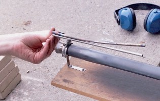
BEND IT LIKE BECKHAM ... er, TITANIUM
The 1/4-inch [6mm] OD Titanium tubing, after a 20-second run in the test shown in
the preceding photo. Here the tested tubing is held against an unheated piece of identical
size for comparison. This would be a serious problem for my pressure probe method, since
we'd never be sure exactly where the end of the tubular probe was positioned in the
tailpipe cross section at a particular moment.
Photo Copyright 2003 Cottrill Cyclodyne Corporation
I think my best hypothesis, though, is that the warp is simply
the result of a temperature difference between one side of the
tubing [nearest the tailpipe wall] and the other side [in or near
the center of the combustion gas stream]. It is already well
established that a significant difference in gas temperature
exists between the outside and inside of the gas stream in a
pulsejet tailpipe. Yes, the whole tube gets hot, but one side
gets a LOT hotter than the other! This could easily account for
some unbalanced relief of stresses in the tubing.
Of course, alert readers may want to suggest other things
I haven't thought of.
The Ti tubing could certainly be used as a sensing tube for
my pressure gauge, if I could get longer pieces, and if the
warping tendency could be eliminated or carefully controlled.
The warping is an important effect because to get meaningful
pressure readings, we need to know almost exactly where in the
pipe we're picking up the pressure to be sensed by the gauge,
and we can never be sure if the end of the sensing probe is
'creeping' during the test period.
Perhaps another time ...
The sample of Inconel Mark sent me went untested. It is much
heavier than any of the smaller pieces [5/8 inch (16mm)
diameter x over 1/16 inch (1.6mm) thick] and is only 6 or 7
inches [152mm to 178mm] long, so I haven't figured out yet
how to get it deep into the tailpipe. If I come up with a
method, I'll test it. Also, I could probably borrow a lathe
again and turn the 'leading edge' down to .020 inch [0.5mm]
thickness, to try to get a fair comparison against the much
smaller SS and Ti tubing we've tried so far. That's the only
way I can imagine coming close to a fair comparison. Inconel
alloys are supposed to be more durable than Titanium in
prolonged high-temperature applications, and are preferred
where weight is not a design issue [unlike Titanium, these
alloys are about the same density as steel or stainless].
It is another fairly expensive material to use.
Other lessons learned
One thing Ben and I discovered fairly early on is how easy
it is to foul up the natural cycle of the DynaJet by putting
a hard, pressure reflecting surface behind it.
As shown in the photos, the metal tube going into the
tailpipe was held in a small 'bench vise'. To my surprise,
When the end profile of the jaws 'covered' about half the
exhaust path at a distance of about 1.5 inches [38mm] from
the tailpipe exit, the DynaJet was impossible to start, even
though good bangs and short loud pulsing blasts were
obtained! With the vise at a distance of approximately 2.5
inches [63mm] out, the engine would start with a fair amount
of difficulty, but would only run 2 or 3 seconds before
fading away and dying. To me, astonishing results!
The solution was to lower the vise as much as possible, so
that the top edge of the jaws were no higher than a level
approximately in line with the bottom of the tailpipe. With
that configuration, it was possible to start the jet and
obtain a normal run, even with the test material almost all
the way inside the tailpipe and the vise really close in,
as in the setup below [again, using Titanium]:
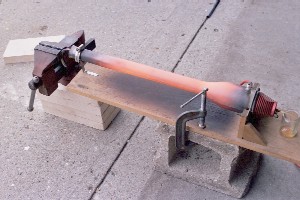
HOW LOW CAN YOU GO?
Another test of 1/4-inch [6mm] OD Titanium tubing, about as deep in the
tailpipe as we could figure out how to place it. The bent end of the tube
was turned down, so that the top of the vise could be dropped as low as
possible [actually lower than it appears from this viewpoint]. With the
vise this close in, it was impossible to start the engine with the jaws
higher in relation to the rear opening of the tailpipe.
Photo Copyright 2003 Cottrill Cyclodyne Corporation
Lesson learned: Reflection of the exhaust 'pressure wave'
back into the tailpipe does make a difference!
Another interesting finding was that I was able to use my
automotive pressure/vacuum gauge to measure the mean value
of venturi suction at the intake throat of the DynaJet. The
gauge showed almost exactly 1 inch Hg [25mm Hg] suction,
holding rock steady throughout the run. To me, this seemed
pathetic, not even getting close to the 'green range' for
an automotive piston engine; however, this would represent
several inches of fuel lift, so it is quite adequate for the
job that needs to be done. Also, remember that this is the
average over time of an intermittent process, so the peak
suction could be twice this value, or possibly even more.
The only difficulty in using the gauge was making sure the
end of the sensing tube was at the right spot in the venturi
-- this is not particularly easy with a handheld device, so
there is some probability of positioning error; the result
reported here should be taken as a rough measurement.
So, another lesson learned: In my opinion, this does show
once again that meaningful measurements of pulsejet action
can be made with a standard pressure gauge of appropriate
sensitivity and range [admittedly, with some interpretation
required.]
Conclusions and future directions
Obviously, creating metal subassemblies that work well inside
the hottest parts of a pulsejet will not be an easy
undertaking. Stainless or even regular mild or high-strength
steels would appear to work well in cooler parts, such as the
region near the tailpipe exit. Titanium might work well for
parts that are small, or any parts where some 'creep' of the  exact shape is inconsequential to performance [e.g. a 'glow
coil' or a small flameholder]. Something like Titanium can't
be welded to dissimilar metals around it, so such parts would
have to be mounted in an engine using bolts or other types of
fasteners.
I don't know when I'll get to do it, but sometime, I'll try
one more test with the DynaJet: Back to the SS tubing, but
coated inside and out with burned-on high temperature flux
[designed for welding]. What you would do for a more complex
internal jet structure is fabricate your part, then keep
heating it dull red hot and plunging it into the powdered
flux and re-heating it [or, you can just make a paste and
coat the whole part first, then melt it on with the torch,
by bringing one small region at a time up to red heat].
Eventually, the whole part would look like it's coated with
a thin layer of black glass, but who cares, as long as this
enables it to hold up inside your engine? I know from
experience that this coating is VERY durable [even though it
runs out quite thin] and forms a smooth and tight coating on
the part, actually resembling black anodizing. And, while a
black surface naturally absorbs heat very well, it also
radiates it very well. So, this could be the answer for a
practical pressure gauge probe [as I was after], or even a
fairly complex internal engine structure. We'll see.
_____________________________________________________
Photo Credits:
All photos in this article were provided by, and are property of,
the author.
_____________________________________________________
Larry Cottrill is a pulsejet designer, builder and experimenter
and Editor of jetZILLA ezine, living in the State of Iowa, USA.
To contact him about this article, email: Editor@jetzilla.com
_____________________________________________________
exact shape is inconsequential to performance [e.g. a 'glow
coil' or a small flameholder]. Something like Titanium can't
be welded to dissimilar metals around it, so such parts would
have to be mounted in an engine using bolts or other types of
fasteners.
I don't know when I'll get to do it, but sometime, I'll try
one more test with the DynaJet: Back to the SS tubing, but
coated inside and out with burned-on high temperature flux
[designed for welding]. What you would do for a more complex
internal jet structure is fabricate your part, then keep
heating it dull red hot and plunging it into the powdered
flux and re-heating it [or, you can just make a paste and
coat the whole part first, then melt it on with the torch,
by bringing one small region at a time up to red heat].
Eventually, the whole part would look like it's coated with
a thin layer of black glass, but who cares, as long as this
enables it to hold up inside your engine? I know from
experience that this coating is VERY durable [even though it
runs out quite thin] and forms a smooth and tight coating on
the part, actually resembling black anodizing. And, while a
black surface naturally absorbs heat very well, it also
radiates it very well. So, this could be the answer for a
practical pressure gauge probe [as I was after], or even a
fairly complex internal engine structure. We'll see.
_____________________________________________________
Photo Credits:
All photos in this article were provided by, and are property of,
the author.
_____________________________________________________
Larry Cottrill is a pulsejet designer, builder and experimenter
and Editor of jetZILLA ezine, living in the State of Iowa, USA.
To contact him about this article, email: Editor@jetzilla.com
_____________________________________________________
|
![Steel tubing forming shower of sparks from DynaJet exhaust [closeup] - photo (c)
2003 Cottrill Cyclodyne Corp.](Steel_sparks_closeup_crop1.jpg)
![Basic concept drawing for proposed Low-Speed Ramjet engine [version I] (c) 2003 Larry Cottrill](http://www.cottrillcyclodyne.com/Low_Vel_Ramjet.gif)
![Basic concept drawing for proposed Low-Speed Ramjet engine [version II] (c) 2003 Larry Cottrill](http://www.cottrillcyclodyne.com/Low_Vel_Ramjet2.gif)